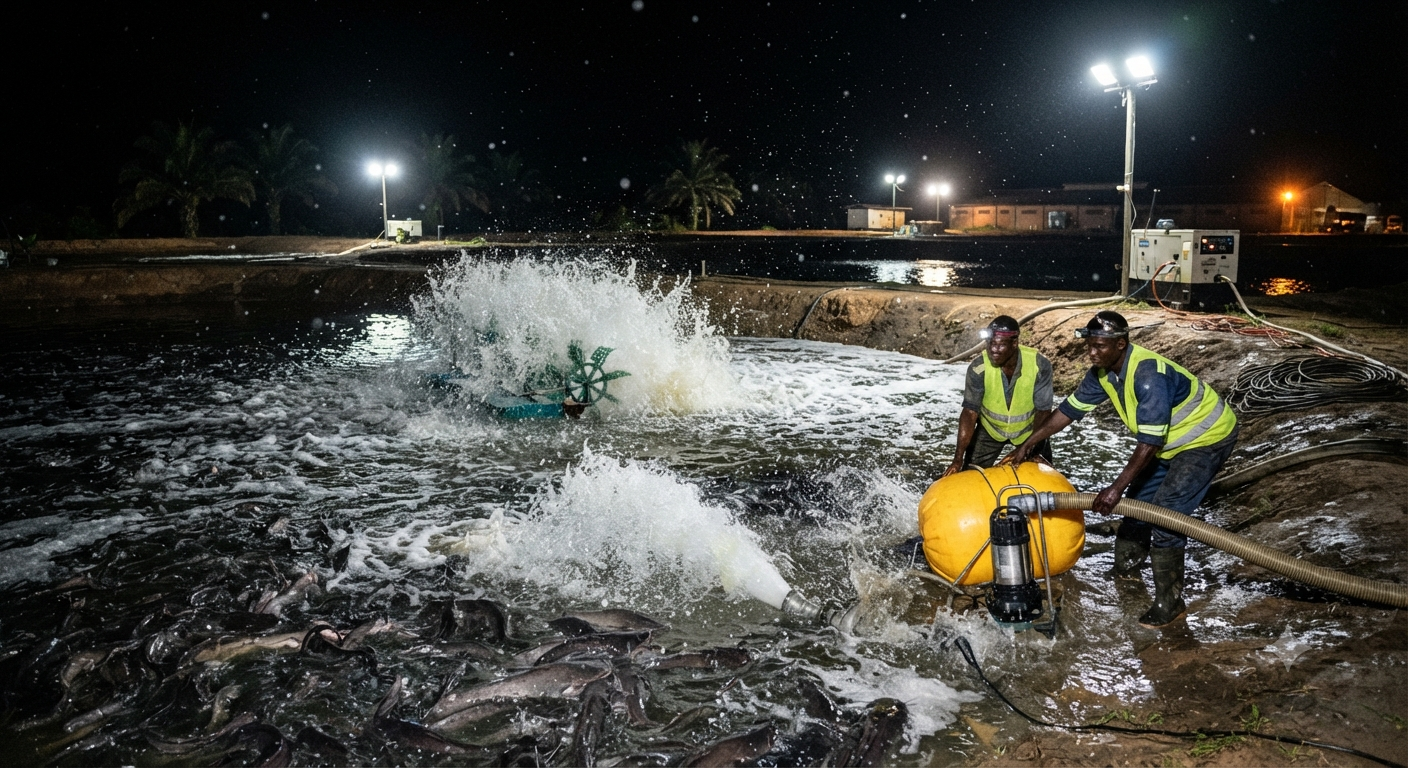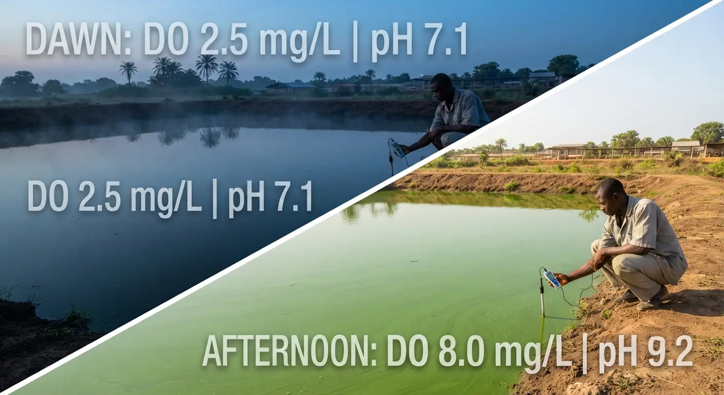
The fundamental constraint in any flow-through catfish production system — whether in an earthen pond or a concrete tank — is water. You can only stock as many fish as the water exchange rate will support without ammonia, nitrite, or dissolved oxygen dropping below critical thresholds. If water supply is limited, stocking density is limited. If stocking density is limited, production per unit of land area is limited. Every management refinement in a flow-through system is ultimately bounded by this constraint.
Recirculating aquaculture systems (RAS) exist to remove this constraint. By treating and reusing the same water rather than discarding it and replacing it with fresh supply, RAS allows fish to be stocked at densities that would produce lethal water quality within hours in an unfiltered system. The biological and mechanical processes in the filtration train continuously remove the waste products that fish produce — converting toxic ammonia to benign nitrate, removing solid waste before it decomposes, replenishing dissolved oxygen — and return clean, oxygenated water to the fish tanks in a continuous cycle.
Understanding what each component of the filtration train does, how to size it correctly for the planned fish biomass, how to establish it before fish are stocked, and how to maintain it through a production cycle is the difference between a RAS that functions at its design capacity and one that fails in ways that range from poor production performance to catastrophic fish losses. The filtration technology is commercially available and well-understood — the management discipline required to operate it consistently is where most commercial RAS operations experience their real challenges.
The RAS Filtration Train — System Architecture
What Must Be Removed From Recirculating Water
Fish in a closed recirculating system continuously add four categories of waste to the water:
Suspended solids: Feces, uneaten feed particles, shed mucus, and dead biological matter that reduce water clarity, consume oxygen as they decompose, and provide substrate for pathogen growth. If not removed mechanically, these solids accumulate, and their decomposition generates the ammonia and oxygen demand that would otherwise be manageable.
Dissolved ammonia (TAN): The primary metabolic waste from protein catabolism — directly toxic at low concentrations, as covered in the previous article. In a recirculating system without biological filtration, ammonia accumulates until it reaches toxic levels within hours to days depending on biomass density.
Carbon dioxide (CO₂): Fish respiration produces CO₂ that dissolves in water, forming carbonic acid and reducing pH. Without CO₂ removal (degassing), CO₂ accumulates to levels that impair fish respiration and blood pH regulation even when dissolved oxygen is adequate.
Nitrite (NO₂⁻): The intermediate product of biological ammonia oxidation — accumulates if the nitrification process is incomplete or disrupted.
The filtration train addresses each of these in sequence:
Mechanical filtration → Biological filtration → CO₂ degassing → Oxygenation → UV/ozone (optional)
Each stage removes one category of waste — and each stage is a prerequisite for the next to function correctly. Mechanical filtration must precede biological filtration because suspended solids clog biological filter media and increase the oxygen demand within the biofilter to levels that suppress the nitrifying bacteria. Biological filtration must precede oxygenation because adding oxygen to ammonia-loaded water simply allows a higher fish biomass to produce more ammonia — the oxygen addition is only productive when the ammonia has already been converted by the biofilter.
Mechanical Filtration — Removing Suspended Solids
Why Mechanical Filtration Is First in the Train
Mechanical filtration is the first processing step after water leaves the fish tanks — removing the solid particles that would otherwise:
- Accumulate and decompose, generating ammonia and oxygen demand that overloads the biological filter
- Clog the porous media in the biofilter, reducing its surface area and biological activity
- Reduce water clarity, affecting fish behavior and feed detection
- Provide substrate for pathogen growth and biofilm formation
The standard measure of a mechanical filter’s performance is turbidity (Nephelometric Turbidity Units, NTU) — a well-functioning mechanical filter should reduce incoming turbid tank water to below 5–10 NTU before it enters the biofilter.
Drum Filters (Microscreen Filters)
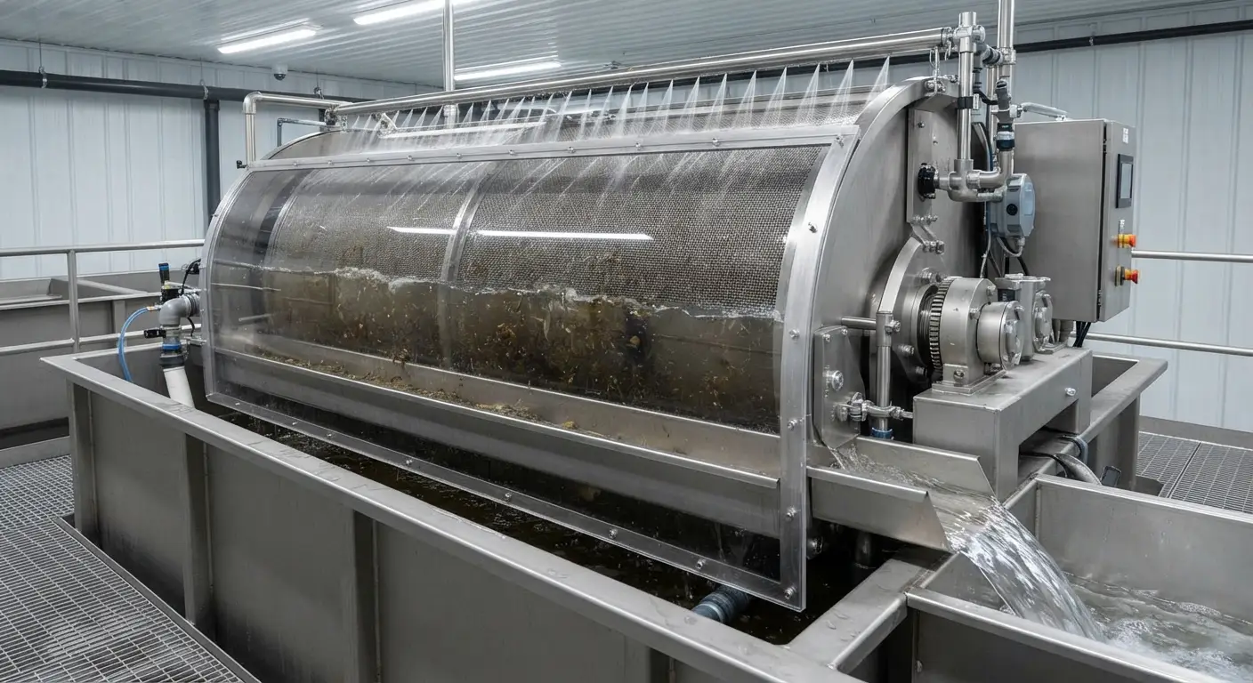
The most effective and most widely used mechanical filtration technology in commercial RAS — a rotating drum of fine mesh screen (typically 60–200 micron opening) that captures suspended solids as water flows through the screen surface. The drum rotates continuously, and the accumulated solids on the screen are removed by a high-pressure backwash spray that washes them into a waste collection channel.
How drum filters work:
- Water enters the inside of the rotating drum and passes outward through the mesh screen
- Solids larger than the screen opening are retained on the inside screen surface
- As the drum rotates, the solids-loaded section of screen passes under the backwash nozzles, which wash solids off the screen into a waste trough
- Clean screen continues to rotate into the incoming water flow
Sizing drum filters:
Drum filter capacity is rated in flow rate (m³/hour) and solids loading (kg total solids per day). Both must be specified for the intended fish biomass:
- Daily solid waste production: approximately 40–60 kg of settleable solids per tonne of feed fed
- At FCR 1.4 and 50 kg/day feed input: 70–84 kg/day of solids requiring removal
- Select a drum filter rated above this loading at the farm’s maximum feed input
Screen mesh selection:
- 100 micron mesh: removes most settleable solids; standard for grow-out systems
- 60 micron mesh: higher solid removal efficiency; more frequent backwashing required; preferred for hatchery systems where very high water clarity is critical
- 200 micron mesh: lower backwash frequency; suitable for pre-filtration before a finer filter stage
Drum filter operational requirements:
- Continuous rotation (usually electrically driven, though some gravity-flow designs exist)
- Backwash water supply (typically from the clean water side of the filter circuit, at 2–4 bar pressure)
- Waste discharge collection and treatment (the backwash concentrate is nutrient-rich and requires appropriate management)
- Regular inspection of the screen for damage, tears, or blinding (blockage that prevents backwashing from fully clearing the screen)
Settling Chambers and Radial Flow Separators
Lower-technology alternatives to drum filters — gravity-based settling devices that allow suspended solids to settle out of the water flow before it enters the biofilter:
Settling chambers: An enlarged, low-velocity section of the return pipe or a dedicated chamber where reduced water velocity allows particles to settle to the bottom for periodic removal. Less effective than drum filters at removing fine particles (below 100 micron) but significantly lower capital cost and zero energy consumption for the settling process itself.
Radial flow separators (swirl chambers): A cylindrical tank into which water enters tangentially, creating a slow spiral flow that moves suspended particles to the center bottom of the cylinder for collection. More effective than simple settling chambers for fine particles; still lower capital cost than drum filters.
When to choose lower-technology mechanical filtration:
For smaller RAS systems (below 50 m³ fish tank volume) where the capital cost of a commercial drum filter is difficult to justify, settling chambers or radial flow separators provide adequate mechanical filtration for reasonable fish densities. They require more frequent manual cleaning than automated drum filters but are simpler to maintain and have lower failure risk.
Biological Filtration — The Core of RAS Technology
The Nitrification Process
Biological filtration in RAS is based on nitrification — the two-step bacterial oxidation of toxic ammonia to nitrite, and then nitrite to benign nitrate:
Step 1: NH₃ + 3/2 O₂ → NO₂⁻ + H₂O + H⁺ (performed by Nitrosomonas bacteria) Step 2: NO₂⁻ + 1/2 O₂ → NO₃⁻ (performed by Nitrobacter and Nitrospira bacteria)
The combined result is the conversion of toxic ammonia to nitrate (NO₃⁻), which is approximately 500–1,000 times less toxic than NH₃ and accumulates in the recirculating water until diluted by the daily make-up water addition (5–10% of system volume per day in a well-functioning RAS).
What nitrifying bacteria need:
- Adequate surface area to colonize (they are sessile, attaching to solid surfaces rather than living suspended in water)
- Dissolved oxygen above 2 mg/L at the biofilter surface (nitrification is aerobic — oxygen-deprived biofilters shift to denitrification, producing nitrogen gas and reducing rather than oxidizing ammonia)
- Appropriate pH (nitrification is inhibited below pH 6.0 and above pH 8.5; optimal at pH 7.0–8.0)
- Stable temperature (nitrification rate halves for approximately every 10°C drop below 30°C)
- Protection from disinfectants, antibiotics, and other chemicals that kill the bacterial community
Biofilter Media Types
The biofilter provides the surface area on which nitrifying bacteria grow. The performance of different biofilter media types is expressed in terms of specific surface area (square meters of surface per cubic meter of media volume) and the ammonia removal rate per unit surface area:
Moving Bed Bioreactor (MBBR) media:
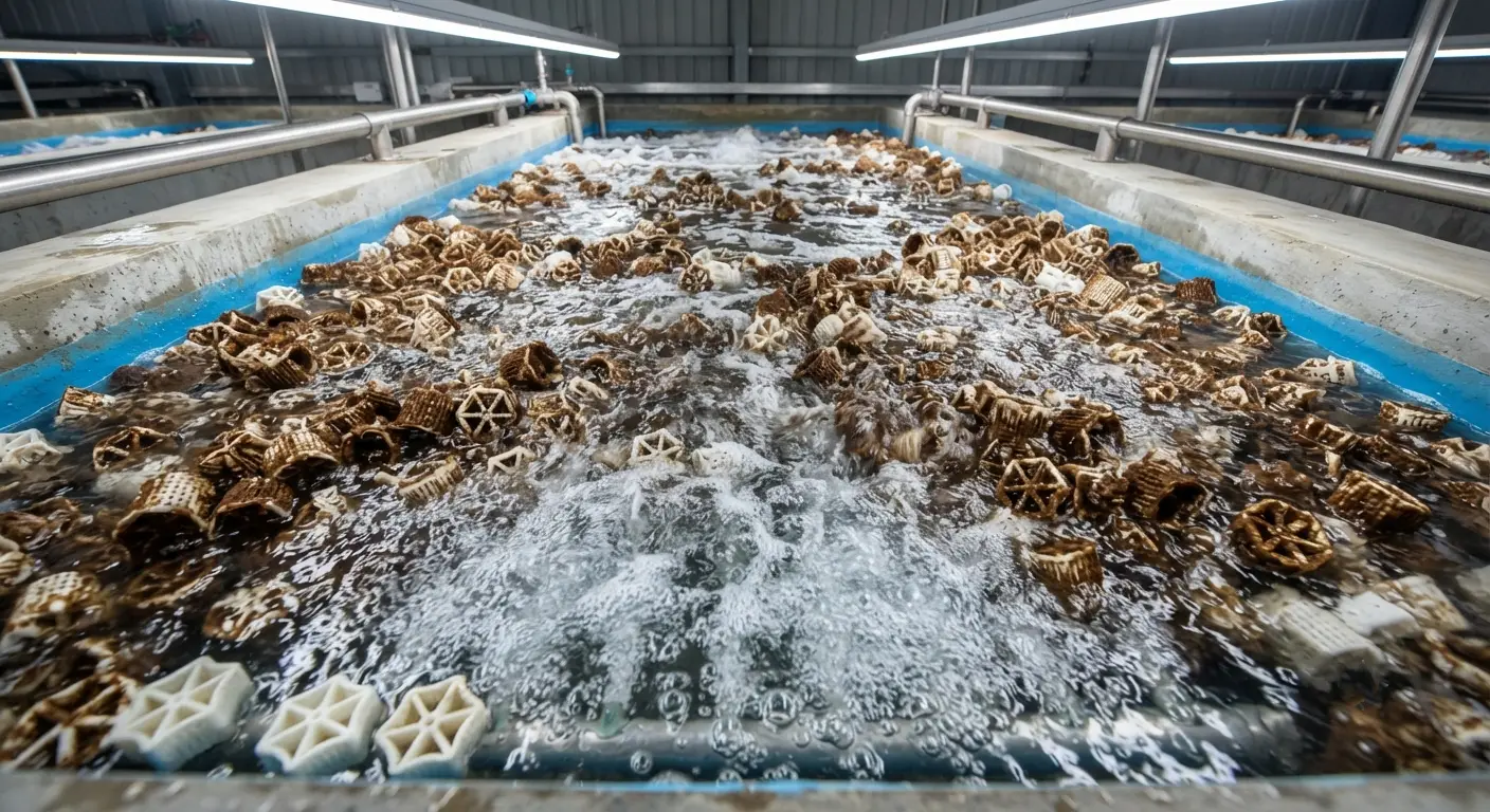
Small plastic carriers (typically 10–25 mm diameter, various shapes — Kaldnes K1, K3, K5, Bioportz and similar designs) that float and circulate freely within the biofilter tank under aeration. The plastic carriers have textured or labyrinthine internal surfaces that provide very high specific surface area (400–800 m²/m³) while the movement of the carriers continuously shears off excess biofilm, preventing clogging and maintaining active biological activity.
MBBR is the most widely used biological filtration technology in modern commercial RAS — it combines high surface area with self-cleaning action (carrier movement) and easy visual monitoring of biofilm health (color and thickness of biofilm on carriers is visible). It does not require backwashing and can be retrofitted to existing tanks.
Trickling filters:
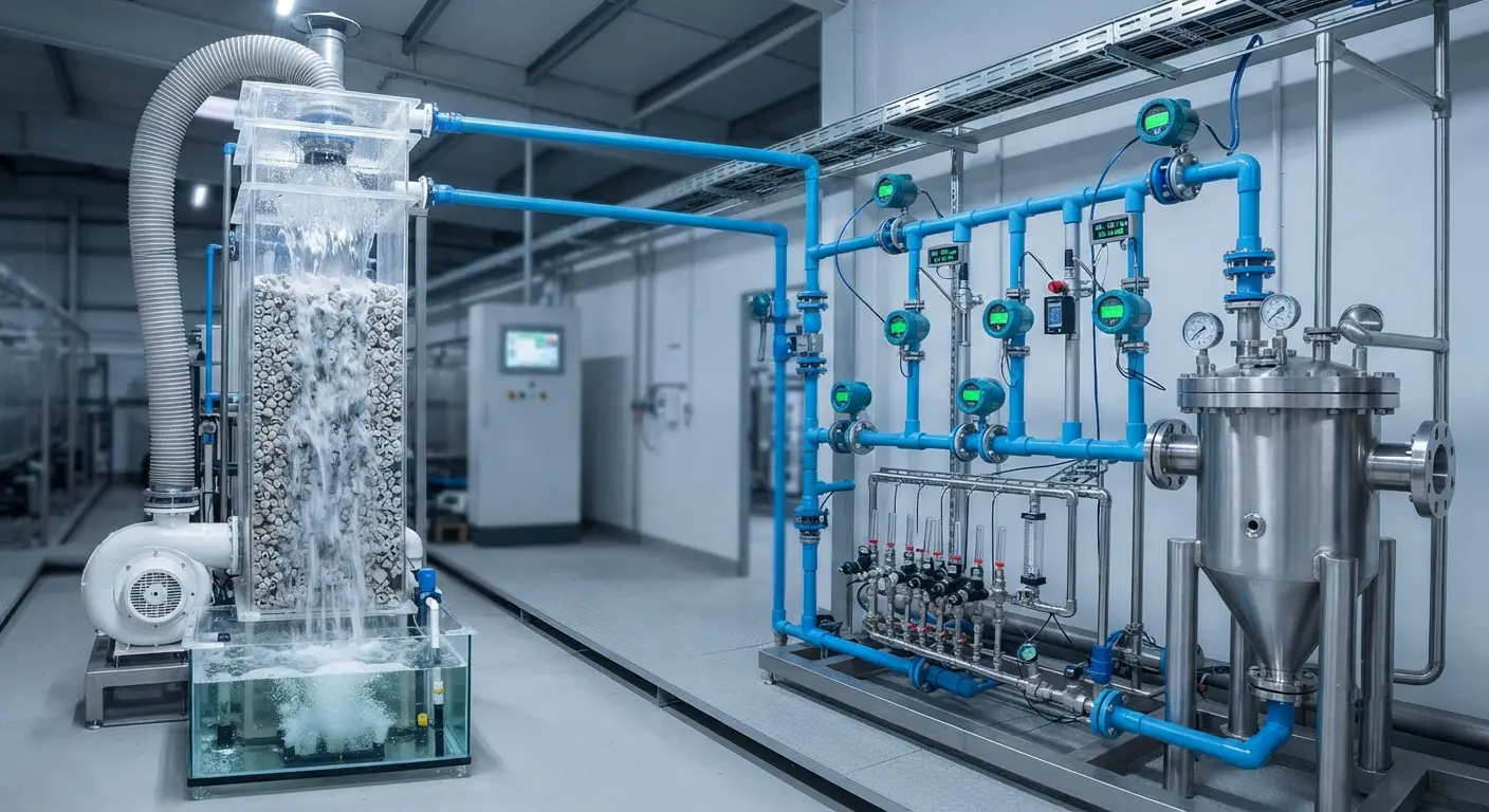
A bed of fixed media (plastic rings, plastic structured packing, or biological balls) over which water flows downward from distribution nozzles above, exposing the biofilm-coated media to both water (carrying ammonia) and air (providing oxygen directly to the biofilm surface). Trickling filters are particularly efficient at CO₂ stripping simultaneously with biological filtration — the air exposure removes dissolved CO₂ from the trickling water sheet.
Less common in new RAS designs than MBBR due to higher blockage risk from solids, but still widely used and very effective when properly managed (requires good mechanical filtration upstream to prevent media clogging).
Submerged fixed-bed filters:
Media fully submerged in water, through which water is pumped upward (upflow) or downward (downflow). Simpler to construct than MBBR or trickling filters; the main limitation is that the fixed media is prone to clogging from solids that pass the mechanical filtration, and backwashing is required to clean the media periodically.
Gravel/sand biological filters:
The simplest and lowest-cost biological filtration approach — a bed of gravel or coarse sand that provides surface area for nitrifying bacteria. Gravel bed filters work adequately at low to moderate ammonia loads but require regular backwashing and have lower ammonia removal capacity per unit volume than media-specific biofilter designs. Appropriate for lower-density systems or as a pre-biofilter step.
Biofilter Sizing
The biofilter must be sized to remove the ammonia produced by the fish biomass at the system’s maximum design capacity. Undersizing the biofilter is the most common RAS design error — it results in ammonia accumulation that limits stocking density to below the designed target.
Sizing calculation:
Daily TAN production ≈ 0.03 kg TAN per kg of feed fed (a standard approximation for high-protein catfish diets)
At FCR 1.4 and 50 kg/day feed: Daily TAN production = 50 × 0.03 = 1.5 kg TAN/day
Target outlet TAN concentration: 1.0 mg/L (ensuring NH₃ below 0.02 mg/L at pH 7.5)
MBBR removal rate: approximately 0.5–1.0 g TAN per m² of effective biofilm surface per day (under good operating conditions)
Required effective biofilm surface area: 1,500 g/day ÷ 0.75 g/m²/day = 2,000 m² effective surface
MBBR media volume required: 2,000 m² ÷ 600 m²/m³ (for K3 media at 60% fill) = 3.33 m³ of media
At 60% fill in the MBBR tank: tank volume = 3.33 ÷ 0.60 = 5.5 m³ MBBR tank capacity
This calculation should be performed for the maximum planned fish biomass at peak feed input — not for a lower biomass level during the early ramp-up of the system. A biofilter sized for early production that is insufficient at peak production creates the ammonia crisis at exactly the time the farm has its highest financial investment in the fish biomass.
System Cycling — Establishing the Biofilter Before Stocking
Why Cycling Is Essential
A new biofilter has no nitrifying bacteria — the biological treatment capacity that is the entire point of the RAS does not exist until the bacterial colony is established. Stocking fish into an uncycled system causes ammonia to rise immediately, with no biological removal pathway — creating acute toxicity within days at any significant fish density.
The cycling process establishes the nitrifying bacterial colony by providing ammonia as a food source while the bacteria colonize the media surface. The process takes 4–6 weeks under optimal conditions — during which the biofilter cannot yet support fish production.
The Cycling Process
Method 1: Fishless cycling (recommended for new installations)
Add ammonia to the empty system without fish, allowing the bacterial colony to establish against a controlled ammonia source without the welfare risk of fish in a toxic environment:
- Fill the system with water and start all pumps, aeration, and the MBBR system
- Add ammonium chloride (NH₄Cl) or pure aqueous ammonia solution to achieve a TAN of 3–5 mg/L
- Measure TAN and nitrite daily
- When nitrite begins to rise (typically after 1–2 weeks), Nitrosomonas has established and is converting NH₃ to NO₂⁻
- Continue adding ammonia daily to maintain TAN at 3–5 mg/L as the bacteria consume it
- When nitrite peaks and then begins to fall (typically after 3–5 weeks), Nitrobacter/Nitrospira has established and is converting NO₂⁻ to NO₃⁻
- When the system can fully convert the added ammonia dose within 24 hours (both TAN and NO₂ remain near zero after each addition), the biofilter is established
- Stock fish at a low initial density (20–30% of designed maximum) and increase over 2–4 weeks
Method 2: Low-density fish cycling
Stock the system at 10–15% of designed maximum density from the beginning, allowing the fish’s own ammonia excretion to drive biofilter establishment while the low biomass keeps TAN below acutely toxic levels. Requires very close monitoring and water exchange backup if TAN rises above 2 mg/L.
Method 3: Transfer from established biofilter
Where an existing established RAS is available, transferring media carrying an established biofilm from the old system to the new system dramatically accelerates cycling — the colonized media provides an immediate biological treatment capacity that reduces cycling time to 1–2 weeks rather than 4–6 weeks.
The Cycling Record
Daily measurements during cycling should be recorded:
| Day | TAN Added (g) | TAN Measured (mg/L) | NO₂ Measured (mg/L) | NO₃ Measured (mg/L) | pH | Notes |
|---|
The pattern of rising then falling nitrite, followed by the disappearance of both TAN and NO₂, is the confirmation that both steps of nitrification are established. Do not stock at full density until this pattern is confirmed across at least 3 consecutive days.
CO₂ Management and Degassing
Why CO₂ Accumulates in RAS
Fish respiration produces CO₂ at a rate approximately proportional to oxygen consumption. In a recirculating system, the same water is repeatedly exposed to fish respiration — unlike flow-through systems where CO₂ is continuously removed with the exchange water, recirculating water accumulates CO₂ with each pass through the fish tank.
At elevated CO₂ concentrations (above 20–30 mg/L), fish develop hypercapnia — elevated CO₂ in the blood that acidifies blood pH and impairs the enzyme activity that controls respiration and metabolism. The consequences are reduced feed intake, impaired immune function, and in severe cases, loss of equilibrium and mortality. The effects of elevated CO₂ can mimic DO stress — fish surface breathe frequently despite adequate dissolved oxygen, because the CO₂-impaired blood cannot efficiently utilize the available oxygen.
CO₂ Removal Methods
Cascade degassing (atmospheric stripping):
Water falls through a structured packing tower (similar in concept to a trickling filter) where the large surface area and counter-current air flow strip dissolved CO₂ from the water into the atmosphere. Effective, passive (no energy input beyond the pump delivering water to the top of the tower), and appropriate for medium to large scale systems.
Venturi stripping:
High-velocity water flow through a venturi creates turbulence that strips CO₂ from the water and releases it to atmosphere. The same venturi used for oxygen addition can be adapted for CO₂ stripping by positioning the air inlet appropriately. Less efficient than a cascade degasser but requires no additional infrastructure beyond the venturi fitting.
Forced air degassing:
A blower forces air through submerged fine-bubble diffusers in the degassing chamber — the air bubbles strip CO₂ from the water as they rise to the surface. More energy-intensive than cascade or venturi stripping but can be placed at any point in the system without requiring elevation head.
CO₂ management target:
Maintain dissolved CO₂ below 15 mg/L in the fish tank water — at 28°C and normal atmospheric pressure, this is well below the threshold for fish health impacts. Measure CO₂ indirectly through pH measurement (rising CO₂ reduces pH through carbonic acid formation) or directly with a CO₂ meter.
Oxygenation in RAS
Oxygen Addition vs. Aeration
In high-density RAS at maximum biomass, simple air-based aeration cannot maintain dissolved oxygen at target levels — the limited oxygen content of air (approximately 21% O₂) and the solubility constraints described in the previous article mean that air-based aeration at typical stocking densities is inadequate.
Liquid oxygen (LOX) or compressed oxygen injection:
Pressurized oxygen gas (from cylinders or an on-site liquid oxygen tank) injected into the water flow achieves DO concentrations above air saturation — typically 12–15 mg/L compared to the air-saturation maximum of 7–8 mg/L at 28°C. This oxygen supersaturation in the return water provides a buffer that maintains fish tank DO well above the minimum threshold even at very high biomass densities.
Oxygen injection methods:
Venturi oxygen injection: The same venturi used for aeration can be fitted with an oxygen supply instead of air — the pressure differential draws oxygen gas into the water stream, achieving efficient dissolution.
Pressurized oxygen reactor: A sealed pressurized vessel into which water and oxygen are introduced under pressure — the elevated pressure dramatically increases oxygen solubility (Henry’s Law), achieving very high oxygen saturation that persists in the water as it returns to ambient pressure in the fish tank. Most efficient oxygenation method for RAS; higher capital cost.
Diffuser oxygen addition: Fine-bubble diffusers release oxygen gas directly into the fish tank or return line — simpler than venturi or pressurized reactor but less efficient (some oxygen bubbles escape before dissolving).
Oxygen consumption rate as a system management metric:
In a functioning RAS, tracking daily oxygen consumption (comparing oxygen supplied against oxygen lost through degassing and fish consumption) provides an indirect measure of the system’s biological activity — including the biofilter’s oxygen demand and the fish biomass’s metabolic rate. Unexpected increases in oxygen consumption can indicate biofilter activity changes (increased organic loading) or fish health events (elevated metabolic rate from disease stress).
UV Sterilization and Ozone Treatment
UV Sterilization
Ultraviolet light at 254 nm wavelength inactivates pathogens by damaging their DNA, preventing reproduction. UV sterilizers in RAS reduce pathogen loads in the recirculating water — reducing the disease transmission that would otherwise be amplified by the water recirculation.
UV sterilizer sizing:
UV effectiveness depends on water clarity (turbidity reduces UV penetration), flow rate through the sterilizer (UV exposure time), and UV lamp output (in mW/cm²). After mechanical filtration, the water should be clear enough for effective UV treatment.
For most commercial RAS applications: a UV dose of 30–40 mJ/cm² is adequate for inactivating most fish pathogens (bacteria, viruses). Select a UV sterilizer with appropriate capacity for the system’s recirculation flow rate.
UV operational management:
UV lamp output declines over time — typically to 60–70% of original output after 8,000–10,000 hours of operation. Lamps must be replaced on schedule, not when visible output declines (UV light is not visible to the human eye). Maintain a lamp replacement record and schedule replacement at the manufacturer-recommended interval regardless of visible condition.
Ozone Treatment
Ozone (O₃) is a powerful oxidizing agent that inactivates pathogens, removes color from recirculating water (water yellowing, called “gilvin” accumulation, is a chronic problem in RAS with minimal water exchange), and oxidizes dissolved organic compounds that contribute to water quality deterioration.
Ozone hazards: Ozone is toxic to fish at concentrations above 0.01–0.02 mg/L and must be fully reduced to oxygen before water returns to fish tanks. Ozone treatment systems must include an activated carbon contact chamber or a reaction tank with sufficient residence time for ozone decomposition before treated water enters the fish tank.
When to consider ozone: In RAS systems with very low water exchange rates (below 5% daily) where color accumulation and dissolved organics cause chronic water quality degradation despite adequate TAN and nitrite management, ozone provides the oxidative capacity to maintain water quality without requiring large water exchange volumes.
RAS Operational Management
Daily Management Protocol
A RAS requires daily management attention across all system components — unlike earthen ponds where a daily water quality check is the primary monitoring requirement, RAS management includes equipment inspection, flow verification, and biological filter health assessment:
| Time | Management Action |
|---|---|
| Morning | Measure DO, TAN, NO₂, pH, temperature in all fish tanks; record in log |
| Morning | Inspect drum filter: backwash functioning? Screen clean? Waste collection clear? |
| Morning | Inspect MBBR: aeration bubbling evenly? Media moving? Biofilm color healthy (dark brown)? |
| Morning | Inspect pumps: all running? Unusual noise or vibration? |
| Morning | Check CO₂ degasser: flow through packing? |
| Morning | Verify UV lamp indicator (if fitted): lamp operating? |
| Morning | Observe fish: feeding response, behavior, any floating or sick fish? |
| Afternoon | Spot check DO and temperature in highest-biomass tanks |
| Evening | Final DO check in all fish tanks; adjust oxygen addition if needed |
Biofilter Health Monitoring
The MBBR biofilm is the most critical biological asset in the RAS — its health determines whether the system can handle its designed ammonia load. Visual and chemical monitoring provides early warning of biofilter stress:
Healthy biofilm signs:
- Dark brown to black coating on the inner surfaces of MBBR carriers
- Carriers moving freely and evenly throughout the MBBR tank
- TAN consistently below 1.0 mg/L in the fish tanks despite normal biomass loading
- NO₂ consistently below 0.3 mg/L
Biofilter stress indicators:
- TAN rising despite stable or declining fish biomass
- NO₂ rising (indicates Nitrobacter suppression — the second nitrification step is impaired while the first continues)
- MBBR media appearing pale brown or yellowish rather than dark brown (indicates insufficient organic loading for biofilm health, or pH stress)
- Unusual odor from the MBBR tank (sulfurous odor indicates anaerobic conditions — oxygen to the biofilter is insufficient)
Response to biofilter stress:
Identify and remove the stressor first — whether it is antibiotic residual in the water (stop any antibiotic treatment immediately and add activated carbon to adsorb residuals), pH drop (lime), temperature drop (check heating), or oxygen depletion in the biofilter (increase aeration to the MBBR tank).
Then reduce fish tank ammonia loading while the biofilter recovers — reduce feed rate, increase water exchange volume above the normal make-up rate, and monitor TAN and NO₂ daily until they return to target range.
System Backup and Emergency Protocols
Power failure: The most acute emergency in RAS — all pumps, aeration, and the drum filter stop simultaneously. Without water circulation, DO in fish tanks drops rapidly toward zero (the fish continue consuming oxygen with no replenishment). Emergency generator with automatic transfer switch is essential — any RAS operating without backup power is one grid failure away from a mass mortality event.
Drum filter malfunction: Solids bypass the mechanical filter and enter the biofilter. Immediate impact is elevated turbidity; developing impact over hours to days is biofilter clogging and ammonia breakthrough. Response: switch to manual settlement system or reduce fish load; inspect and repair drum filter immediately.
Pump failure: Divert water through standby pump or gravity-feed bypass; restore normal flow as soon as possible.
Summary
Recirculating aquaculture systems provide the highest production intensity per unit of land and water of any catfish production system — but that intensity is entirely dependent on the correct design, establishment, and continuous maintenance of the filtration train that makes water reuse possible. The mechanical filter removes solids before they generate additional treatment demand. The biofilter converts toxic ammonia to benign nitrate. The degasser removes CO₂ that would otherwise impair fish respiration. The oxygenation system replenishes the dissolved oxygen that the fish and biofilter continuously consume.
Each component must be correctly sized for the planned maximum fish biomass — not for the biomass at initial stocking but for the peak production density the system is designed to support. Each component must be operational before fish are stocked at production density — the biofilter in particular requires 4–6 weeks of establishment before it can handle full ammonia load. And each component must be monitored daily for the early warning indicators of malfunction that allow corrective action before they cascade to fish health consequences.
The subsequent articles in this series move from water quality and production systems to the biology and management of the fish themselves — beginning with broodstock selection and management for catfish hatcheries.