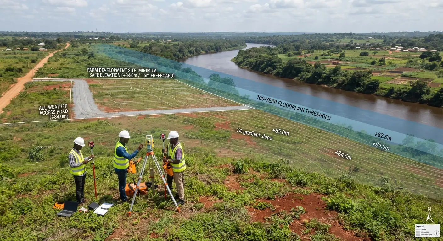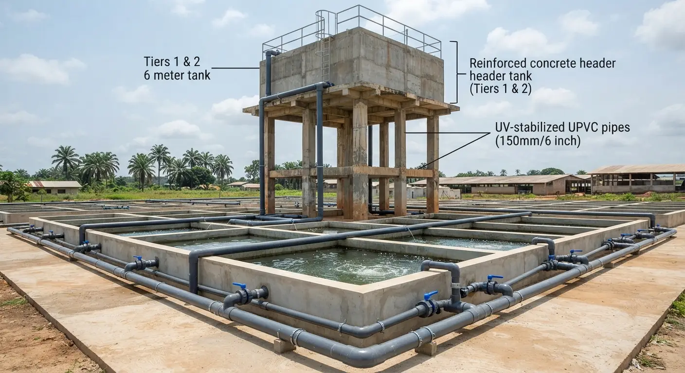
Plumbing and water engineering are the infrastructure that determines whether a catfish farm’s water quality management is easy or perpetually difficult. A correctly engineered water supply system delivers the right volume of water at the right pressure to every tank or pond position. A correctly designed drainage system removes wastewater and allows rapid pond or tank emptying for harvest, without fish mortality from crowding. A correctly sized outlet structure maintains the water level a pond needs while handling the peak rainfall events that would otherwise overtop and breach a pond bund.
The engineering principles involved are not complex; they involve basic hydraulics, pipe sizing calculations, and construction details that are standard in civil and agricultural engineering. What makes them consequential in catfish farming is the biological sensitivity of the production system to failures: a blocked outlet that allows a pond to overflow during a storm event, a pipe that is one size too small and cannot supply the flow rate needed during peak summer temperatures, or a drainage system that takes 6 hours to empty a tank during harvest (leaving fish crowded in shallow water, consuming oxygen, and generating ammonia faster than it can be diluted) all produce direct production losses that dwarf the cost of the correct engineering specification in the first place.
This guide covers every plumbing and water engineering element in a commercial catfish farm system — with specific design criteria, pipe sizing calculations, and the construction details that distinguish systems that function reliably from those that create recurring problems.
Water Supply System Design
The Water Supply Hierarchy
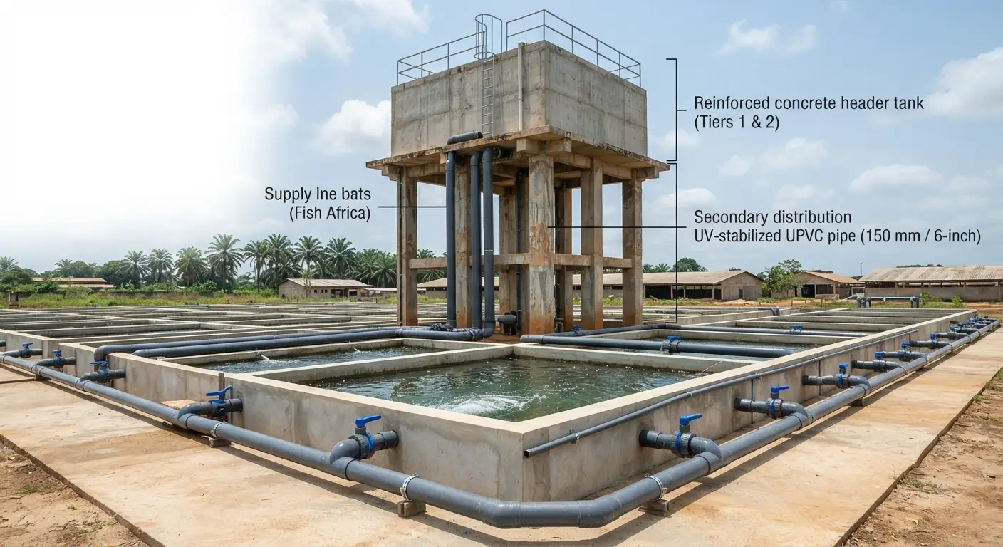
A commercial catfish farm’s water supply system has three tiers that must each be correctly engineered:
Tier 1 — Source to storage: Moving water from the source (borehole, river intake, reservoir) to on-farm storage (header tank, reservoir, or directly to the distribution system).
Tier 2 — Storage-to-distribution manifold: Moving water from on-farm storage to the distribution points serving individual ponds or tanks.
Tier 3 — Distribution manifold to individual units: Delivering water to each pond or tank at the required flow rate.
Each tier has specific design requirements. Failure at any tier compromises the entire supply system.
Flow Rate Calculation — Sizing the System
The first engineering calculation in water supply design is the total system flow rate requirement — the volume of water per unit time that the supply system must deliver to maintain adequate water quality across the entire farm.
For a concrete tank catfish farm:
The daily water exchange requirement for each tank is the product of tank volume and the target daily exchange rate:
Daily exchange (m³) = Tank volume (m³) × Exchange rate (%)
For example, a farm with twenty 50 m³ tanks at 20% daily exchange: Daily water requirement = 20 × 50 × 0.20 = 200 m³/day = 8.33 m³/hour = 2.31 liters/second
The peak instantaneous flow rate must account for the fact that exchange is typically not occurring simultaneously in all tanks at all times — if tanks are exchanged sequentially rather than simultaneously, the peak flow demand at any single moment is the flow rate to the number of tanks being exchanged simultaneously.
For an earthen pond farm:
Daily water requirement = Sum of (evaporation + seepage + exchange) across all ponds
For a 5-hectare total pond area at 8 mm/day combined evaporation and seepage, plus 10% daily exchange of 1.2 m average depth:
- Evaporation + seepage: 50,000 m² × 0.008 m = 400 m³/day
- Exchange: 50,000 m² × 1.2 m × 0.10 = 6,000 m³/day
- Total: 6,400 m³/day = 267 m³/hour = 74 liters/second
Add a safety factor: Design the supply system capacity at 1.5–2.0 times the calculated average flow rate to accommodate peak demand periods, pump maintenance downtime on one pump when multiple pumps are used, and the additional water demand during disease treatment or emergency response.
Pipe Sizing
The most common plumbing engineering failure in catfish farms is undersized pipes that cannot deliver the required flow rate without excessive friction losses and pressure drop. The relationship between pipe diameter, flow rate, and pressure loss follows the Hazen-Williams equation, but a practical simplified approach works for most farm-level design:
Practical pipe sizing guidelines for PVC pipe:
| Flow Rate (liters/second) | Minimum Pipe Diameter (mm) | Notes |
|---|---|---|
| Up to 0.5 | 50 mm (2 inch) | Individual tank supply lines |
| 0.5–2.0 | 75 mm (3 inch) | Section manifold, small farm main supply |
| 2.0–5.0 | 100 mm (4 inch) | Main supply line, medium farm |
| 5.0–15.0 | 150 mm (6 inch) | Large farm main supply |
| 15.0–40.0 | 200 mm (8 inch) | Very large earthen pond systems |
| Above 40.0 | 250–300 mm (10–12 inch) | Industrial scale |
The velocity constraint: Avoid flow velocities above 2.0–2.5 m/second in supply pipes — above this velocity, friction losses increase rapidly (as the square of velocity), significantly reducing deliverable flow at the end of the pipe run. Velocity also increases the risk of water hammer damage to pipe joints and fittings when valves are closed quickly.
Friction loss allowance: For pipe runs longer than 50 meters, account for friction loss in pipe sizing — a pipe that delivers the required flow rate at 20 meters distance may be inadequate at 100 meters distance if the supply pressure is not sufficient to overcome friction losses in the longer run. Use the appropriate pipe sizing tables or the Hazen-Williams equation when designing long pipe runs.
Header Tank Design and Placement
A header tank positioned above the farm’s distribution system — at minimum 2 meters above the highest tank or pond outlet, ideally 4–6 meters — provides several operational advantages:
Gravity-fed distribution: Water flowing by gravity from the header tank to the farm requires no pump energy for distribution, reducing operating costs. The head pressure from the height difference drives flow to all supply points simultaneously without pump operation.
Emergency buffer: A header tank sized for 2–4 hours of farm water demand provides an emergency buffer if the pump fails — fish do not immediately suffer water quality degradation, allowing time for pump repair or emergency response before production impact occurs.
Pressure regulation: Header tanks provide consistent pressure to the distribution system regardless of pump operation cycles, preventing the pressure surges that can damage connections when pump-direct supply systems cycle on and off.
Header tank sizing: Minimum 2 hours of total farm daily demand. For a farm requiring 100 m³/day, the header tank should hold a minimum 8–10 m³ (approximately 10,000 liters).
Header tank construction options:
- Elevated concrete tank (most durable, highest initial cost)
- Elevated steel or fiberglass tank on a structural steel frame (faster construction, requires corrosion-resistant material)
- Elevated plastic tanks (250–10,000 liter capacity, appropriate for smaller operations)
Supply Line Layout
The ring main layout: For farms with multiple tank or pond positions spread across a site, a ring main (loop) supply system — where the supply pipe runs in a loop connecting all supply points rather than branching from a single trunk — provides the most reliable water delivery. If a section of the ring main blocks or fails, water can still reach all supply points via the other half of the loop.
The branching manifold layout: More common in practice for tank farms — a main supply pipe runs along the tank array with branch connections to each tank. Simpler to construct but creates a single-point failure if the main line is compromised.
Individual tank flow control: Each tank supply connection should have an individual valve that allows adjustment of flow rate to that specific tank independently of other tanks — critical for managing stocking density differences between tanks and for isolating tanks during treatment or maintenance without affecting other tanks in the system.
Inlet Structure Design
Tank Inlets
For concrete tanks, the inlet design determines how water is introduced to the tank — and how the introduction of water can be used simultaneously as an aeration mechanism.
Surface spray inlet: Water introduced through a pipe that terminates above the tank water surface, creating a falling stream that entrains air and introduces oxygen as it enters the water. This simple design provides both water exchange and some aeration — particularly effective for the splash that breaks the water surface and promotes oxygen transfer.
Submerged inlet: A pipe that enters the tank below the water surface, avoiding surface disturbance. Used where surface turbulence is undesirable (larval rearing tanks where surface agitation can injure fragile larvae) or where the inlet velocity might disturb settled sludge if directed at the tank floor.
Venturi inlet: A venturi device creates a pressure differential that draws air into the water stream before it enters the tank — delivering pre-aerated water that can significantly increase DO in the receiving tank. The aeration efficiency of a correctly designed venturi inlet is substantially higher than a simple surface spray — investing in venturi inlet fittings on supply lines is a low-cost improvement to aeration capacity that reduces the need for additional mechanical aeration.
Inlet positioning: Position tank inlets to create circular or lateral flow patterns across the tank — water movement helps distribute dissolved oxygen, food, and other parameters uniformly and prevents dead zones where low DO or high ammonia accumulates. For circular tanks, tangential inlet positioning creates a circular flow that also concentrates sludge at the tank center drain.
Earthen Pond Inlet Structures
The concrete inlet structure: The water supply inlet to an earthen pond should be constructed as a permanent concrete structure rather than simply laying a pipe through the bund — for two reasons:
Seepage prevention: Water tends to track along the outside of pipes passed through earthwork (a phenomenon called “piping”) — eventually creating a seepage channel that can undermine the bund. A concrete inlet structure with proper anti-seepage collars prevents this progressive seepage.
Control capability: A concrete structure accommodates a valve or slide gate that allows the inlet flow to be adjusted or shut off — necessary for water level management, partial pond draining, and emergency response.
Inlet elevation: The pond supply inlet should discharge at or above the designed water surface level — water cascading down from the inlet to the pond surface provides oxygen transfer (splash aeration) that partially compensates for the nighttime DO decline described in the pond systems article.
Splash pad at inlet: A concrete splash pad at the point where the inlet water contacts the pond surface distributes the energy of the falling stream and prevents erosion of the pond base and bunds at the inlet point — a simple, low-cost detail that prevents a common structural maintenance problem.
Drainage and Outlet System Design
The Critical Importance of Drainage Engineering
Drainage engineering failures are more consequential than supply failures in catfish production — if water cannot be removed from a pond or tank at the required rate, harvest operations are compromised (fish crowded in shallow water as the water level falls slowly), water quality management is constrained (water exchange rate limited by drainage capacity), and emergency response to water quality problems (rapidly dropping the water level to add fresh water) is impossible.
Concrete Tank Drainage Systems
The bottom drain: A drain positioned at the lowest point of the tank floor is the most practical drainage approach for rectangular or circular concrete tanks. The bottom drain allows complete tank emptying by gravity (where the drain outlet is lower than the tank floor) — typically to an external drain channel or treatment facility.
Drain sizing: The time to empty the tank during harvest determines harvest efficiency. A 50 m³ tank should be drainable in 30–45 minutes for practical harvest operations — calculate the required drain pipe diameter from the target drainage time and tank volume:
Flow rate needed = Tank volume ÷ Target drain time = 50 m³ ÷ 0.5 hours = 100 m³/hour = 27.8 liters/second
From pipe sizing guidance: a 150 mm (6 inch) pipe at gravity drainage velocity can deliver approximately 20–35 liters/second depending on head available — appropriate for this drain time target.
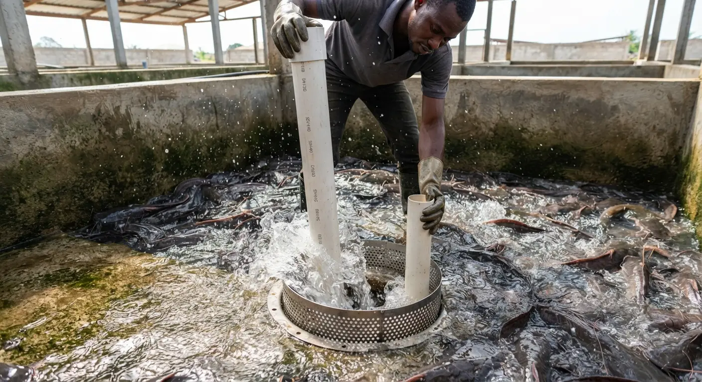
Water level control (standpipe/riser pipe system): Rather than a valve that controls drainage directly (which requires staff to operate during continuous water exchange management), the most practical water level control in concrete tanks is a standpipe system:
A standpipe — a vertical pipe section that can be raised or lowered within the drain connection — sets the water level by acting as an overflow: water rises until it reaches the top of the standpipe and overflows into the drain. To lower the water level (for harvest or increased exchange), the standpipe height is reduced. To maintain a fixed water level, the standpipe is set at the target depth and left in place.
This system allows continuous passive water level maintenance without staff attention — water automatically overflows when it reaches the standpipe height, requiring no active management during normal operation.
Screen at the drain: All tank drains must have a screen or grate to prevent fish from being lost through the drainage system. Screen mesh size should be appropriate to the size of the smallest fish in the tank (half the body depth of the smallest fish is a practical mesh size guideline). Screens require regular cleaning — blocked screens reduce drainage rate and can cause tank overflow.
Earthen Pond Drainage Systems
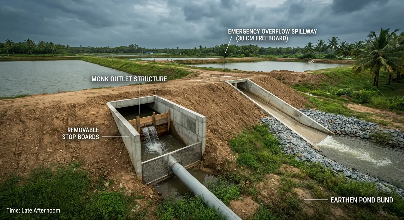
The monk structure (pipe and board outlet): The traditional and most practical outlet structure for earthen ponds in catfish production is the monk — a rectangular concrete chamber built into the downstream (lower elevation) bund, with a series of grooves that accommodate removable wooden boards.
The water level in the pond is controlled by the height of boards stacked in the monk’s inner grooves — water overflows the top of the board stack into the drain pipe that exits through the bund. To lower the water level, boards are removed from the top until the board height matches the target water level. To drain the pond for harvest, all boards are removed simultaneously — the pond drains by gravity through the drain pipe.
Monk design dimensions for a 0.5-hectare pond:
- Internal chamber dimensions: 1.0 m × 0.8 m minimum (allows a person to enter for board management)
- Board slot grooves: two sets of grooves (inner set for water level control, outer set for a screen to prevent fish loss during normal overflow)
- Drain pipe diameter: 300–400 mm for complete pond drainage in 6–8 hours
- Concrete thickness: minimum 150 mm for structural integrity in earthen bund penetration
Anti-seepage collar: The drain pipe passing through the bund must have an anti-seepage collar — a concrete flange wider than the pipe diameter — at the point where it penetrates the bund material. This collar forces any water that begins to track along the pipe surface to navigate around the collar rather than directly through, preventing the progressive seepage channel formation described in the inlet section.
Emergency overflow spillway: Every pond must have an emergency overflow spillway — a defined pathway through which water can safely exit the pond if the water level rises above the designed maximum (from unexpected rainfall, blocked outlet, or supply control failure) without overtopping and eroding the bund. An uncontrolled bund overtop — where fast-flowing water cuts through the bund material — can cause catastrophic bund failure and total loss of the pond’s water and fish.
The spillway is typically a section of the bund constructed at a lower elevation than the rest (20–30 cm lower than the bund crest) and protected with concrete or riprap (compacted stone) to resist erosion — water overflows through this designated point rather than cutting through wherever the bund happens to be lowest.
The Drainage Collection System
All drainage from the farm — pond overflow, tank exchange water, harvest drainage, cleaning water — must be collected and managed rather than released directly to the environment:
Settlement pond: A settlement pond (excavated basin into which all farm drainage flows) allows suspended solids (feces, uneaten feed particles, algae) to settle out of the drainage water before it is discharged or recirculated. Settling removes the oxygen-demanding organic load from the effluent — reducing the environmental impact of discharge and, where water is recirculated, preventing accumulated solids from returning to production ponds.
Minimum settlement pond size: 5–10% of total pond area served, with a minimum residence time of 24 hours at the maximum drainage flow rate.
Effluent quality requirements: In many jurisdictions, aquaculture effluent must meet standards for suspended solids, biochemical oxygen demand (BOD), and ammonia before discharge to natural waterways. Verify applicable regulations before designing the discharge system.
Aeration Engineering
Aeration as a Water Engineering Element
Aeration is not simply an emergency response to low dissolved oxygen — it is an integral component of the water engineering system that determines the sustainable stocking density and production intensity of any catfish farm. The aeration capacity designed into the farm infrastructure sets the maximum biomass the system can safely support.
Aeration Rate Calculation
Oxygen demand from fish: African catfish at 28°C consume approximately 250–350 mg of oxygen per kilogram of fish body weight per hour (higher at elevated temperatures, higher post-feeding, lower at night). A tank holding 500 kg of fish at 28°C consumes approximately 125–175 g of oxygen per hour = 3.0–4.2 kg per day.
Oxygen input from water supply: Water entering the tank at DO saturation (approximately 8 mg/L at 28°C) carries dissolved oxygen that partially meets the demand. For a tank with 20% daily exchange of 50 m³:
- Exchange volume = 10 m³/day = 0.417 m³/hour
- DO delivered = 0.417 m³/hour × 8 g/m³ = 3.3 g/hour = 80 g/day
The gap between oxygen demand (3,000–4,200 g/day) and oxygen supplied by water exchange (80 g/day) must be met by aeration — illustrating that water exchange alone is entirely insufficient for DO management in intensively stocked systems.
Aeration equipment selection:
Paddlewheel aerators: Most effective for large pond surfaces — the rotating paddle wheel beats the water surface, creating turbulence that maximizes oxygen transfer from air. Standard efficiency for commercial paddlewheel aerators: 1.5–2.5 kg oxygen per kWh of electrical energy. Most practical for ponds above 0.1 hectare.
Venturi aerators: Create a high-velocity water jet that draws air in through a restricted throat — the air-water mixture provides efficient oxygen transfer for the jet volume. Lower noise than paddlewheel; effective for tank systems and smaller ponds.
Diffused air systems (air blower + air stones or membrane diffusers): An air blower delivers pressurized air through a distribution network to submerged diffusers that release fine bubbles throughout the tank or pond depth. Highly efficient oxygen transfer (fine bubbles have high surface area to volume ratio); well-suited to rectangular tanks where surface aerators would create undesirable water turbulence.
Liquid oxygen injection: Pressurized liquid oxygen injected directly into the water supply line or tank achieves very high DO concentrations (above saturation) in a small water volume — most appropriate for RAS systems and high-density nursery tanks.
Minimum aeration capacity specification: Provide sufficient aeration to maintain DO above 5 mg/L throughout the tank or pond at maximum designed biomass loading, measured during the pre-dawn period when DO is at its daily minimum. Calculate required aerator capacity as the difference between oxygen demand and supply (from water exchange), with a 1.5× safety factor.
Pipe Materials and Fittings
PVC (Polyvinyl Chloride)
The most commonly used pipe material for aquaculture applications in West Africa — PVC pipe is durable, resistant to corrosion and biological fouling, smooth bore (low friction losses), available in a wide range of diameters and pressure ratings, and relatively inexpensive compared to alternatives.
Selection criteria:
- Pressure rating: select pipe with pressure rating at least 2× the maximum system pressure; for gravity-fed systems (typical on most farm supply lines), standard pressure PVC (PN6 or PN10) is adequate; for pumped systems with significant pressure, use higher-rated pipe
- UV resistance: unplasticized PVC (UPVC) degrades over time in direct sunlight, becoming brittle and failing prematurely; where pipes are exposed to direct sunlight, use UV-stabilized UPVC or protect with paint or insulating wrap
HDPE (High-Density Polyethylene)
An alternative to PVC with superior impact resistance and flexibility — HDPE pipe is more resistant to cracking from impact or ground movement, making it preferable for buried supply lines or in locations with variable soil conditions. Higher cost than PVC but longer service life in demanding applications.
GI (Galvanized Iron)
Traditional pipe material still used in some farm installations for high-pressure sections and pump connections. Galvanized iron rusts over time in wet conditions — the rust products (iron oxides) can elevate water iron concentrations and cause fish gill irritation at high levels. Not recommended as a primary material for supply lines in new installations; replace existing GI pipe with PVC or HDPE as opportunity arises.
Fittings and Joints
Solvent-welded PVC joints: The most reliable joint for PVC pipe — chemical solvent fuses the pipe and fitting surfaces into a monolithic connection with pressure rating equivalent to the pipe itself. Correct application (applying solvent to both surfaces, assembling quickly, allowing full cure time before pressurizing) produces leak-free joints; incorrect application (insufficient solvent, attempting to join wet surfaces, insufficient cure time) produces the persistent minor leaks that are frustrating to locate and repair.
Rubber compression fittings: Allow connection to existing pipe without solvent, useful for connections to concrete structures or for temporary installations. Less reliable than solvent-welded joints under sustained pressure; not recommended for buried supply lines.
Valves: Every supply line should include isolation valves that allow sections to be shut off for maintenance without disrupting the entire system. Ball valves (quarter-turn) are most practical for sizes up to 100 mm; gate valves for larger sizes. Specify PVC or stainless steel valve bodies — brass valves can leach zinc into aquaculture water at levels toxic to fish at elevated temperatures.
Common Engineering Mistakes and How to Avoid Them
Mistake 1: Undersized Supply Pipes
The error: Installing supply pipes based on immediate demand without accounting for future expansion or peak flow requirements.
The consequence: Supply pressure inadequate at distant tank positions; inability to exchange water fast enough during hot weather or high disease risk periods; system cannot support additional tanks if production is expanded.
Prevention: Size supply pipes at 2× calculated current peak demand; design the distribution manifold for future extension.
Mistake 2: No Emergency Overflow on Ponds
The error: Constructing earthen pond bunds without a designed spillway, relying on the bund crest uniformly to resist any overtopping.
The consequence: During heavy rainfall events, water overtops the lowest section of the bund, cuts through the earthwork, and causes catastrophic bund failure with total loss of water and fish.
Prevention: Every pond requires a designed, armored spillway positioned 20–30 cm below the bund crest at one designated point.
Mistake 3: No Anti-Seepage Collars on Pipe Penetrations
The error: Passing inlet and outlet pipes through bunds without anti-seepage treatment.
The consequence: Progressive seepage channel formation along the pipe surface eventually develops into a piping failure — a growing channel through the bund that accelerates until the bund breaches.
Prevention: All pipe bund penetrations must have anti-seepage collars; the pipe should be embedded in compacted, puddled clay for at least 1 meter on each side of the penetration.
Mistake 4: Screens Too Large for Fish Size
The error: Installing drain screens with mesh openings larger than appropriate for the fish size in the tank.
The consequence: Fish escape through the drain, particularly during the night or when disturbed, with both production loss (lost fish) and welfare consequences (fish in drain channels typically die).
Prevention: Screen mesh opening should be half the body depth of the smallest fish expected in the tank; screens should be inspected daily and replaced when damaged.
Mistake 5: Single Pump Without Backup
The error: Installing a single water supply pump without a backup — assuming the pump will not fail during production.
The consequence: Pump failure during peak summer conditions creates an acute water quality emergency within hours; no water supply means no DO management, no ammonia dilution, and potential mass mortality within 12–24 hours in intensively stocked tanks.
Prevention: Always install a minimum of two pumps (either two identical units with one on standby, or two units each capable of delivering at minimum 60% of required flow as partial backup); maintain pump spare parts inventory on-farm.
Mistake 6: No Flow Measurement Capability
The error: Operating a water supply system without any means of measuring actual flow rates to individual tanks or ponds.
The consequence: The farm manager cannot verify that the designed exchange rate is actually being delivered; changes in supply system performance (from partial blockages, pressure changes, or pump degradation) go undetected; water quality management targets based on assumed flow rates may be missed without detection.
Prevention: Install flow meters on main supply lines; at minimum, use simple bucket-and-stopwatch flow measurement on individual tank supply valves during routine inspection rounds.
Summary
Water engineering — the design and construction of supply systems, inlet structures, drainage systems, and aeration infrastructure — is the physical foundation of catfish farm water quality management. The biological management techniques covered in the water quality articles that follow this one are only as effective as the engineering infrastructure that delivers water, removes waste, and maintains oxygen throughout the production system.
The specific design criteria in this guide — pipe sizing at 2× calculated demand, header tanks providing 2–4 hours of emergency buffer, emergency overflow spillways on every pond, anti-seepage collars on all bund penetrations, drain standpipe systems for passive water level control, dual pump installation — are the engineering specifications that distinguish farm infrastructure that functions reliably over a multi-year production life from infrastructure that creates recurring operational problems requiring constant attention and emergency repair.
Get the engineering right at construction. The fish will produce the revenue that recovers the investment. Poor engineering that compromises production — through supply failures, drainage limitations, or aeration inadequacy — generates costs that accumulate every production cycle for the life of the farm.